Introduction
The FrSky Remote NFC Panel is a convenient tool that can safely control the power supply by utilizing a set switch on the radio to enable/disable the power connection remotely, or by the switchboard using NFC Panel while having the device (RB unit, PowerSwitch, etc.) with battery always connected. This kit is composed of a Remote NFC Panel base and NFC Key. Quickly combine all parts, now you can simply utilize the NFC key or the functional switch to manage the power supply without having to plug in/unplug the battery!
Overview

Specifications
● Dimension: 33×19×6.2mm(L×W×H)
● Weight: 10.2g
● Operating Voltage Range: 4-38V
Features
● Supports remote power control by ETHOS radios
● Safe and contactless NFC switch On/Off design
● Avoid the hassle of plugging in / unplugging the battery
● The power is enabled by default while the NFC base panel is connected
How to use the Remote Switch feature?
Preparations
● RemoteNFC Firmware: Ver. 20241109 or later versions.
● ETHOS: Ver. 1.6.1 or later versions
STEP 1
Please make sure the receiver has been registered and bound to the ETHOS radio at first;


STEP 2
Connect the Remote NFC panel to the radio by the S.Port; (Please ensure the firmware of the device is upgraded to the latest version.
STEP 3
Move to the【Device Config】menu and enter into the【Remote NFC】tool interface in ETHOS;

STEP 4
Enable the【Wireless】mode and set an application channel for the Remote feature;


STEP 5
Press【Bind】to bind the Remote NFC panel to the radio;

STEP 6
Poping up a window displaying "Bind OK" means the setting of the Remote feature is completed;

STEP 7
Press【Bind card】to initiate binding the RemoteNFC module to the unique NFC key.

STEP 8
When a notice says "Please hold the NFC key close to the RemoteNFC panel for binding…", please place the NFC key onto the RemoteNFC panel's recognition areas.

STEP 9
If it says "Bind NFC card successfully!", it indicates that your NFC key binding procedure has been completed.

STEP 10
Move to the【Mixes】menu and create a new Mixer, then select a Switch input for the corresponding function channel;

STEP 11
Lastly, replug the Remote NFC panel to the Switch port of the receiver/RB device to complete the setup.
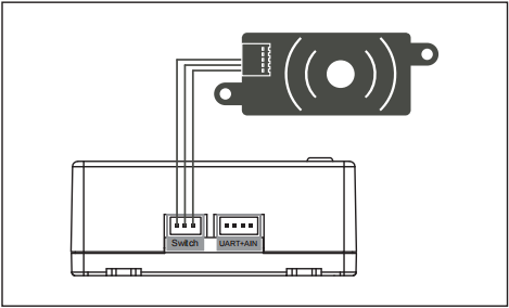
Note:
1. To switch the Power on remotely for the system while the Remote switch and NFC panels are
in status off, please toggle the Switch of Remote feature to On and then Power on the NFC panel
by the NFC key.
2. Power in status On: Both the Remote switch and NFC panels are in status On; Power in status
Off: Either the Remote switch or NFC panels is in status Off;
Introduction The FrSky Remote NFC Panel is a convenient tool that can safely control the power supply by utilizing a set switch on the radio to enable/disable the power connection remotely, or by the switchboard using NFC Panel while having the device (RB unit, PowerSwitch, etc.) with battery always connected. This kit is composed of […]
4. Stabilization Receiver Six-Side Calibration
Each stabilization receiver has undergone six-side calibration before leaving the factory and can be used directly without calibration upon receipt. If the stabilization function of the receiver malfunctions or fails, it will be necessary to recalibrate the receiver. The calibration procedure is as follows:
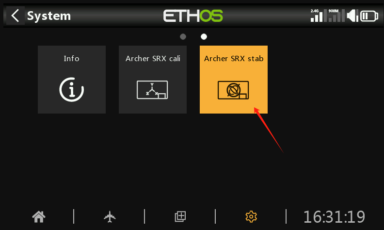
① Enter the SRX stab icon
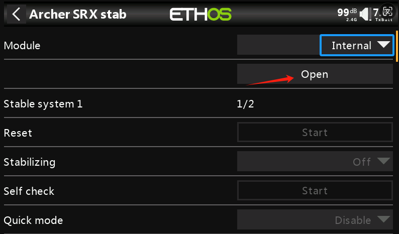
①-①. First, select the Module RF Mode. If the receiver is bound using the internal RF module of the transmitter, choose Internal; if bound with an external high-frequency module, choose External. After selecting the RF mode, click Open, then exit the menu.
② Enter the SRX Cali icon
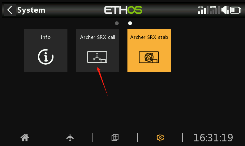
②-① As in steps 1-1, select the Module RF Mode.
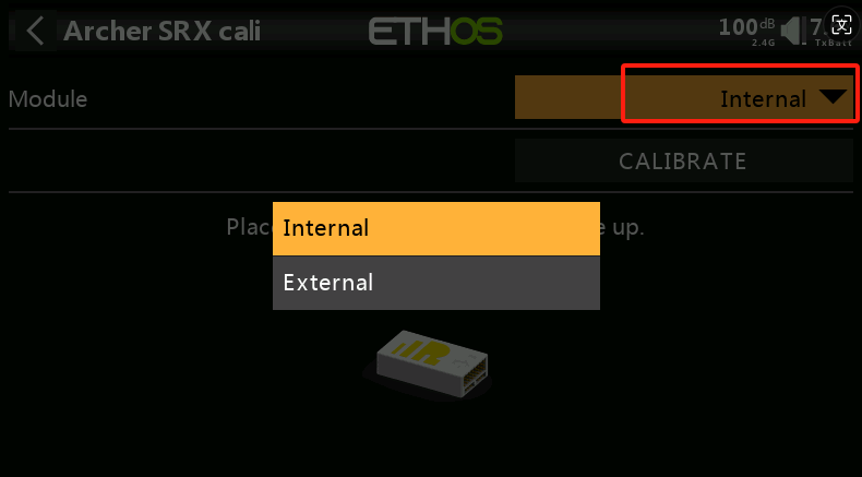
②-② After selecting the RF mode, position the receiver as shown in the (with the logo facing up and the pins to the right) for the first side calibration. Click CALIBRATE to complete the calibration for the first side.
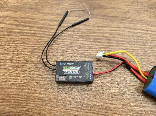
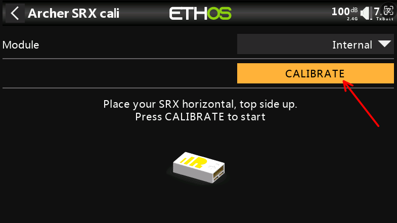
②-③ Position the receiver as shown in the diagram (with the logo facing down and the pins to the right) for the second side calibration. Click CALIBRATE to complete the second side calibration.
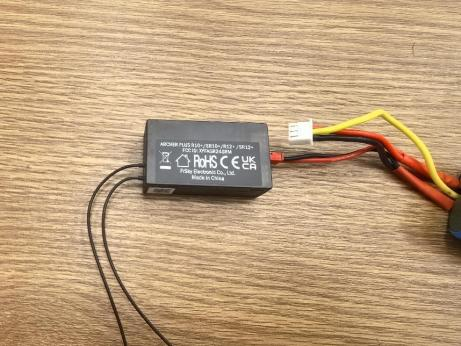
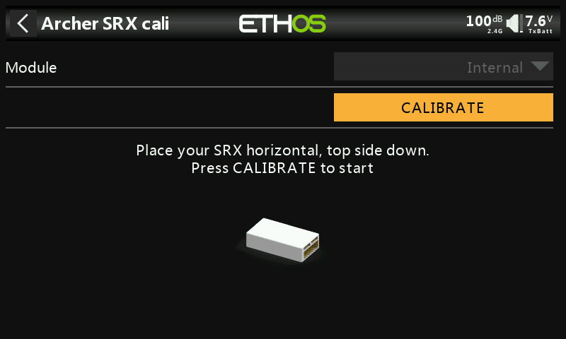
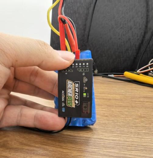
②-④ Position the receiver as shown in the diagram (with the logo facing you and the pins pointing upward) for the third side calibration. Click CALIBRATE to complete the third side calibration.
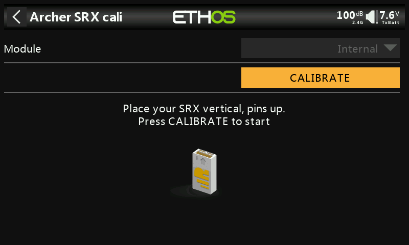
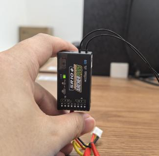
②-⑤ Position the receiver as shown in the diagram (with the logo facing you and the pins pointing downward) for the fourth side calibration. Click CALIBRATE to complete the fourth side calibration.
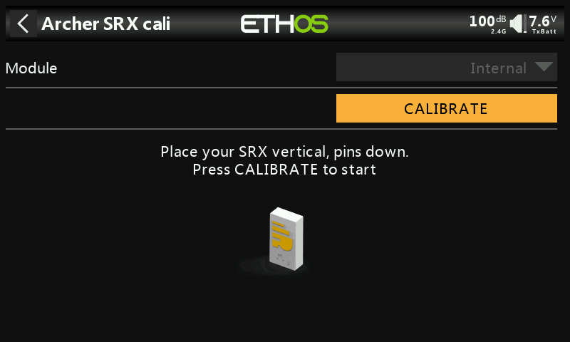
②-⑥ Position the receiver as shown in the diagram (with the logo facing you and the pins to the right) for the fifth side calibration. Click CALIBRATE to complete the fifth side calibration.
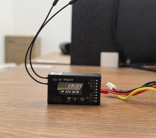
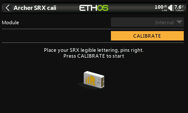
②-⑦ Position the receiver as shown in the diagram (with the logo facing you and the pins to the left) for the sixth side calibration. Click CALIBRATE to complete the sixth side calibration.
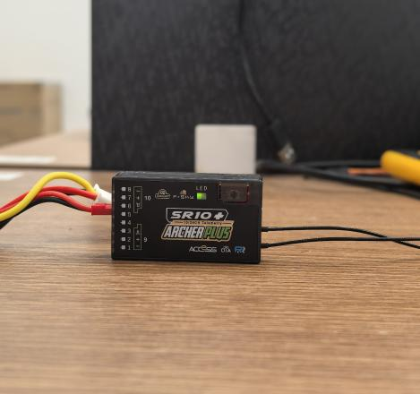
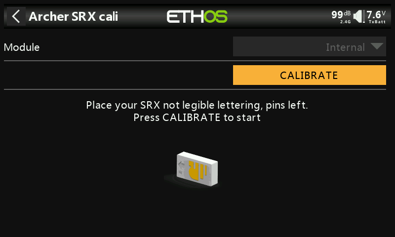
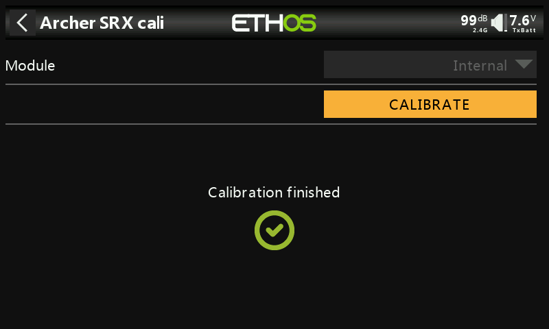
②-⑧ Calibration complete.
5. Stabilization Parameter Adjustment
① Click the SRX stab icon.
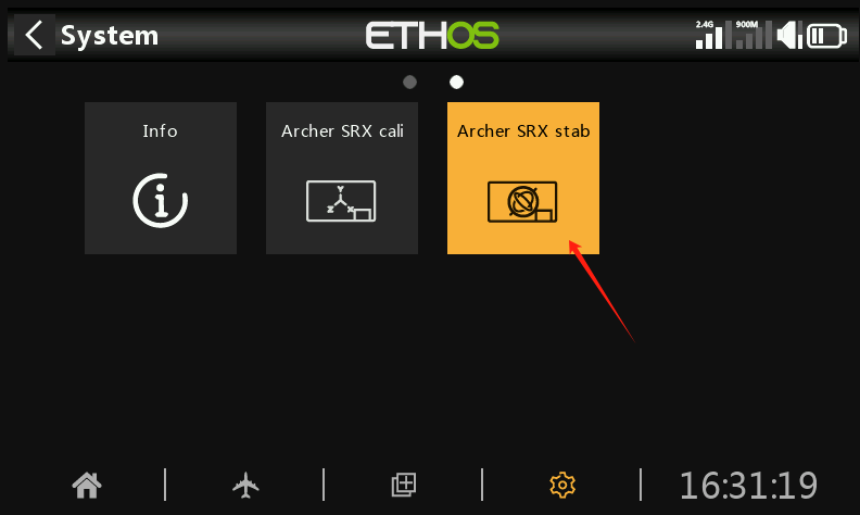
② The stabilization parameter adjustment interface consists of two pages.
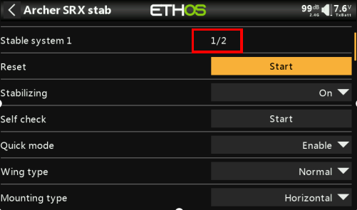
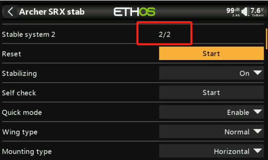
②-① Press the middle button on the left side of the transmitter to switch between pages. Short press to move to the next page, and long press to go back to the previous page.
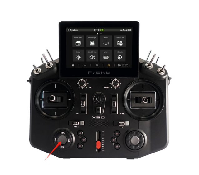
②-② The first page allows you to enable/disable the first set of stabilization channels (CH1-6), while the second page allows you to enable/disable the second set of stabilization channels (CH7-11).
Note 1: The stabilization settings on both pages are independent. If you need to perform a Self-check calibration, each page must be calibrated separately.
Note 2: If only CH1-6 is being used and CH7-11 is not, there's no need to set stabilization for CH7-11 on the second page.
③ The following two photos show the stabilization parameter adjustment contents for the first and second pages.


Stabilization Parameter Adjustment Explanation:
- Module: If the receiver is bound using the internal RF module of the transmitter, select Internal; if bound with an external high-frequency module, select External, then click ‘OPEN’ to access the stabilization parameter adjustment page.
- Reset: Clicking ‘Start’ will reset the stabilization parameter settings on both pages to their factory defaults. Please proceed with caution.
- Stabilization Function: Toggle stabilization on (enable) or off (disable).
- Self-Check: Click ‘Start’ to begin calibrating the stick travel for each channel. This is typically used before the first flight or when the stick channel travel behaves abnormally in stabilization mode. The steps are as follows:
a. Place the aircraft in a level position, set the throttle to the lowest position, and leave the other channels centered.
b. Select Self Check and click ‘Start’. The blue LED will light up. When the blue LED starts blinking, immediately move the three stick channels (except the throttle) to their full travel range to calibrate the maximum travel (excluding the throttle).
c. After completing the stick movements, release all sticks. When the blue LED stops blinking, the receiver's servos will move back and forth, indicating that the calibration is complete.
- Quick Mode: The stabilization function has two flight modes: Enable (Quick Mode) and Disable (Traditional Mode).
a. In Quick Mode, there are only three modes: Manual (stabilization off), Stabilized, and Auto-Level. This mode is switched via CH14, as shown in the diagram (for traditional fixed-wing, delta-wing, and V-tail fixed-wing).

b. Traditional Mode includes five modes: Stabilized, Auto-Level, Hover, Knife-edge, and Manual (stabilization off). This mode is switched using the CH14 & CH15 combination, as shown in the diagram (only applicable to traditional fixed-wing).

c. Traditional Mode for delta-wing and V-tail fixed-wing includes three modes: Stabilized, Auto-Level, and Manual (stabilization off). This mode is switched via CH14, as shown in the diagram.

- Wing Type:
Options: Normal (Traditional Fixed-Wing), Delta (Delta-Wing), VTail (V-Tail Fixed-Wing)
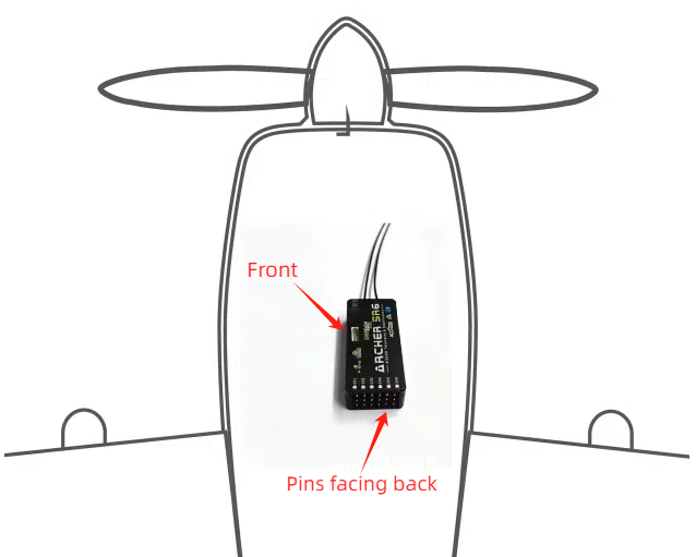
- Installation Orientation: Refer to the picture for receiver installation options:
Horizontal (Logo facing up, pins facing back)、Horizontal reverse (Logo facing down, pins facing back)、Vertical (Logo facing left, pins facing back)、Vertical reverse (Logo facing right, pins facing back)
- CH1-6 Mode on Page 1 & CH7-11 Mode on Page 2, you can choose to use the self-stabilizing function of the corresponding channel or customize (non-self-stabilizing), as shown in the picture:
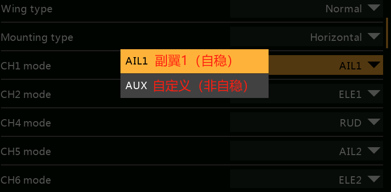
Note: When a channel is set to AUX, it becomes a regular channel without stabilization and can be used for devices like flaps or landing gear.
- Stick (Aileron, Elevator, Rudder) Reversal: In stabilization mode, the channel travel can be reversed, On (reverse on), Off (reverse off)
- Stabilization Sensitivity: Adjustment of sensitivity in stabilization mode.
- Auto-Level Sensitivity: Adjustment of sensitivity in auto-level mode.
- Tilt/Pitch Angle Limit: No effect from 0-10°, with a maximum setting of 80°. If set to 80°, the tilt angle at full stick deflection will be 80°. This function only works in auto-level mode (technically, the angle limit function replaces the auto-level mode function).
- Stick Forward/Reverse Travel Priority: as shown in the picture:
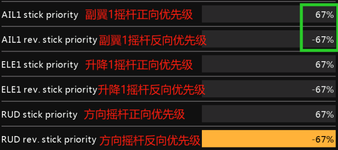
If the forward travel value of aileron 1 is set to 67%, then within 67% of the forward travel on the aileron 1 channel, it will be in stabilization mode. If it exceeds 67%, it will switch to manual mode.
The same applies to reverse travel. If set to -67%, within -67% of reverse travel, it will be in stabilization mode, and below -67% it will switch to manual mode.
Note 1: This function works in stabilization, auto-level, hover, and knife-edge modes.
Note 2: If the Tilt/Pitch Angle Limit is enabled, this function will not work in auto-level mode.
Note 3: The Tilt Angle Limit corresponds to Aileron and Rudder Priority; the Pitch Angle Limit corresponds to Elevator Priority.
6. Aircraft Stabilization Function Tuning Process:
(On the ground) First, tune the receiver in “Auto-Level Mode” (set all trims to 0, and do not adjust the trims yet—just check if the control surfaces are correct and if they reverse when moving the sticks. If any surfaces are reversed, correct them directly on the parameter adjustment page, no need to level them). After tuning, switch to Manual Mode. If any surfaces are unlevel within a 50us range, use the trim buttons to adjust. If the deviation exceeds 50us, it must be adjusted mechanically. Afterward, perform a Self Check (the self-check applies to all modes). Finally, conduct a test flight in Auto-Level Mode to check for any unlevel control surfaces. If there are any, adjust the Auto-Level Trim in the parameter adjustment script. Once this is done, the process is complete.
Note: Before using the new self-stabilization script, make sure to delete the previous script, as the two cannot coexist.
4. Stabilization Receiver Six-Side Calibration Each stabilization receiver has undergone six-side calibration before leaving the factory and can be used directly without calibration upon receipt. If the stabilization function of the receiver malfunctions or fails, it will be necessary to recalibrate the receiver. The calibration procedure is as follows: ① Enter the SRX stab icon ①-①. […]
Introduction: This article only explains the setup operation of the stabilization function. For product introduction and precautions, please refer to the manual.
Before starting the article, let’s first clarify the difference between stabilization and self-leveling in stabilization mode.
Stabilization: Without stick input, it compensates for disturbances (such as wind) to maintain the current flight attitude. (Note: It cannot completely resist external forces, but compensation can be adjusted by modifying the gain to a certain degree.)
Self-Leveling: Without stick input, the flight attitude always keeps the aircraft in a level position. (Note: It cannot completely resist external forces but strives to maintain a level position.)
- Applicable Stabilization Receiver Models
- Preparation
- Mixing Settings
- Stabilization Receiver Six-Side Calibration
- Stabilization Parameter Adjustment
- Aircraft Stabilization Function Debugging Process
1. Applicable Stabilization Receiver Models
This article only covers receivers that support the new stabilization script. The currently supported receivers for the new stabilization script are as follows:
TD Series Receivers: TD SR6、TD SR10、TD SR12、TD SR18
TW Series Receivers: TW SR8、TW SR10、TW SR12
ARCHER PLUS (AP) Series Receivers: AP SR6 Mini / SR6 Mini-E、AP SR8、AP SR10+、AP SR12+
2. Preparation (Using the X20 transmitter and AP SR10+ receiver as an example)
- Please ensure that the X20 system version is 1.5.0 or above, the RF version is ≥ 2.2.6, and the receiver firmware version is ≥ 1.0.11.

Note 1: It is recommended to update the RF version to the latest.
Note 2: Different receiver models may require different firmware versions. It will be compatible as long as the receiver is updated to a version that supports the V3.0.0 script.
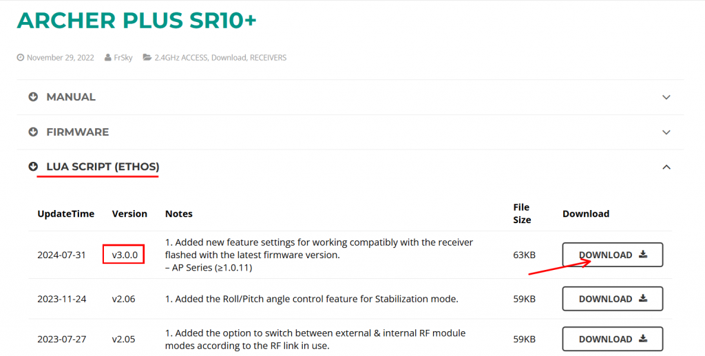
2. Go to FrSky's official website, locate the download page for the corresponding receiver, and download the latest Lua script (current version V3.0.0). After downloading, extract the files.
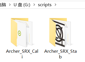
3. Connect the transmitter to the computer via the bootloader interface and access the transmitter's storage. In the root directory of the transmitter's memory, locate the 'scripts' folder (if it does not exist, please create it manually).

4. Place the extracted 'Lua script' files into the 'scripts' folder.
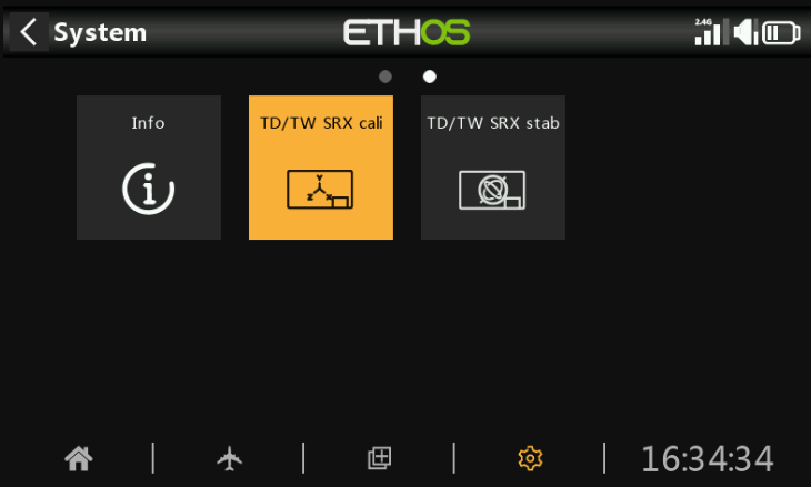
5. After importing, restart the transmitter. The stabilization tuning icon will appear on the second page of the [System Settings] menu, as shown in the image below:
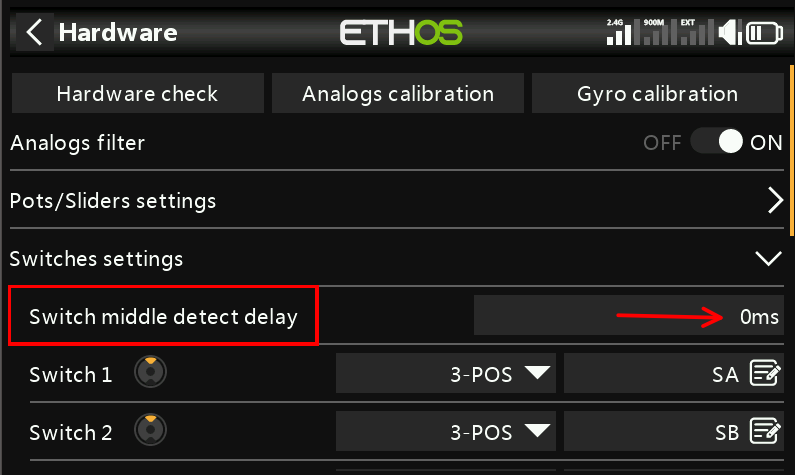
6. To avoid the impact of switch detection delay, please ensure that "Hardware — Switch Settings — Switch Midpoint Detection Delay is set to 0".
3. Mixing Settings
1. The stabilization channel settings in the mixing page are divided into three types of aircraft: traditional fixed-wing, delta-wing, and V-tail fixed-wing. Each aircraft type corresponds to different assigned channels.
1-1 The channels for fixed-wing aircraft are shown in the image below:
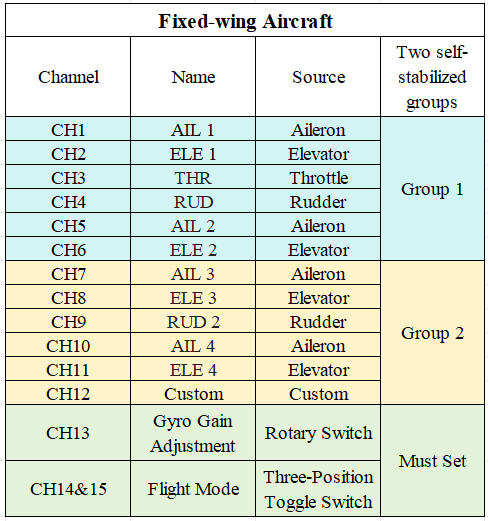
Note: The image shows all channels corresponding to the stabilization function. Users do not need to set up all channels—only the ones required for their specific needs.
1-2 The channels for the delta wing are shown in the image below:
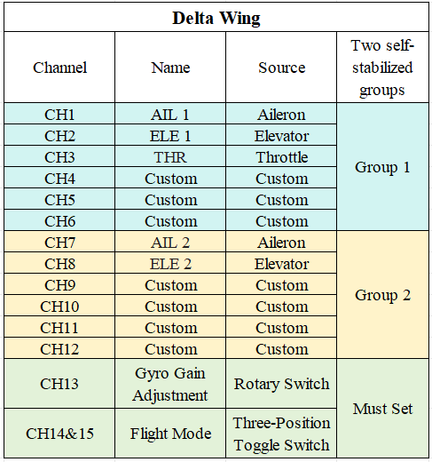
Note: The image shows all channels corresponding to the stabilization function. Users do not need to set up all channels—only the ones required for their specific needs.
1-3 The channels for the V-tail fixed-wing are shown in the image below:
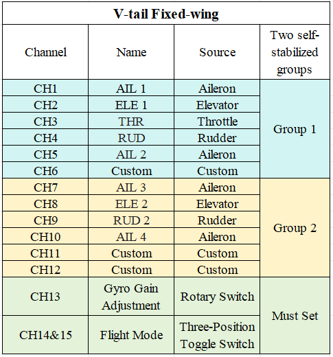
Note: The image shows all channels corresponding to the stabilization function. Users only need to configure the channels required for their specific setup and do not need to set up all channels.
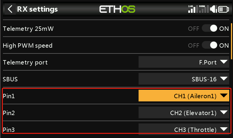
2. Bind the transmitter and receiver. After binding, users can change the "Pin" definitions to the desired channels in the receiver settings (ignore this step if channel changes are not needed).
Introduction: This article only explains the setup operation of the stabilization function. For product introduction and precautions, please refer to the manual. Before starting the article, let’s first clarify the difference between stabilization and self-leveling in stabilization mode. Stabilization: Without stick input, it compensates for disturbances (such as wind) to maintain the current flight attitude. (Note: It […]
· Supported Receiver Types
· Operating Steps
1. Supported Receiver Types
The receiver’s built-in voltage measurement only supports measuring the total battery voltage. To measure individual cell voltage, please use a voltage sensor.
a. Conditions for receivers that support built-in power battery voltage measurement:
- The receiver must have an AIN2 port.
- Currently, there are two voltage measurement ranges: 0-30V and above can be used; 0-3.3V cannot be used directly and requires an external voltage sensor.
Note: Please refer to the corresponding receiver’s manual for confirmation, as shown in the image below.


2. Operating Steps
①. Bind the receiver with the transmitter. After binding is complete, power off both devices.
②. As shown in the image below, connect the receiver's AIN2 port to the positive terminal of the power battery, and connect the receiver's negative terminal to the negative terminal of the power battery.

Note: Please do not connect incorrectly, as this may damage the equipment.
③. With the receiver powered on, press [MDL] on the transmitter, then select [Telemetry] to enter the telemetry interface.

④. Select [Delete All] and then click [Start] to refresh the interface.


⑤. Locate [ADC2] in the telemetry interface; this represents the power battery voltage.

⑥. If the displayed voltage does not match the actual voltage, select [ADC2], then go to Edit— Adjust Voltage Divider Ratio for calibration.

· Supported Receiver Types · Operating Steps 1. Supported Receiver Types The receiver’s built-in voltage measurement only supports measuring the total battery voltage. To measure individual cell voltage, please use a voltage sensor. a. Conditions for receivers that support built-in power battery voltage measurement: – The receiver must have an AIN2 port. – […]
The ETHOS system has been released for some time, and to help everyone easily understand how to update the receiver firmware, we are now releasing a tutorial. Welcome to learn.
Before upgrading to a new version, please make sure to back up the current version's content to avoid any data loss.
· Receiver Wired upgrade
· Receiver Wireless (OTA) upgrade
Using the X20 transmitter and TD R10 receiver as an example:
Receiver Wired update operation
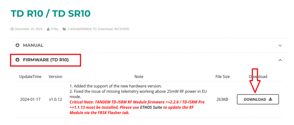
1. Visit the official website at www.frsky-rc.com, locate the firmware download page for the corresponding receiver (TD R10), find the required firmware under the "FIRMWARE" section, and download and extract the file.
2. Enter the bootloader mode on the transmitter and connect it to the computer. Once the computer recognizes the transmitter’s TF card, open the drive and place the extracted firmware file into the root directory of the memory card, as shown in the picture.

3. After importing the file, disconnect the transmitter from the computer. Turn on the transmitter, go to [System Menu→File Manager], and you will see the receiver firmware.

4. Use the connection cable provided with the receiver (some receivers may require a separate cable) to connect the receiver and the transmitter via the S.Port.
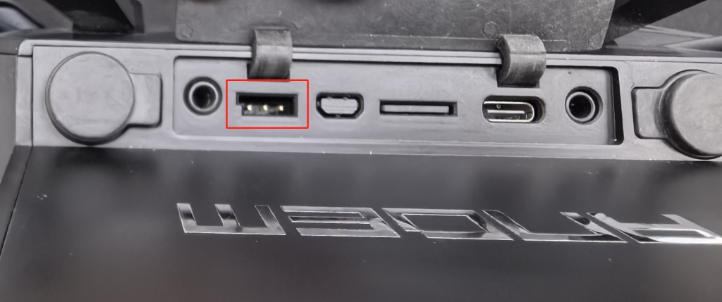
Note: The pinout of the transmitter's S.Port from left to right is defined as Signal (closest to the notch), Positive (middle), and Negative (farthest from the notch).

Note: Please refer to the receiver's manual for its pin definitions. You can refer to the labels in the diagram: "S" (Signal), "+" (Positive), "–" (Negative).
5. Select the receiver firmware, press the [Enter] button to bring up the prompt, and choose "Flash external device" to start the update process.

6. Once the update is successful, click "Close" to complete the process.

Receiver Wireless (OTA) upgrade operation
Please first check the manual to confirm whether the "receiver model in use" supports the "wireless OTA update" function. If it does not support this feature, please disregard this tutorial.
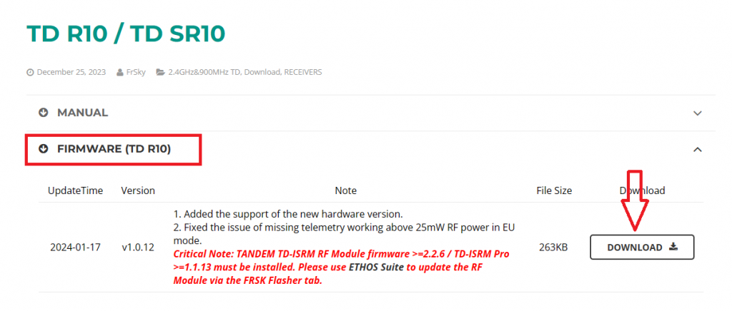
1. Visit the official website at www.frsky-rc.com, locate the firmware download page for the corresponding receiver (TD R10), find the required firmware under the "FIRMWARE" section, download and extract the file.
2. Enter the bootloader mode on the transmitter and connect it to the computer. Once the computer recognizes the transmitter’s TF card, open the drive and place the extracted firmware file into the root directory of the memory card, as shown in the image.

3. After importing the file, disconnect the transmitter from the computer. Turn on the transmitter, enter to "RF System," select the appropriate protocol for 'TD MODE,' and complete the receiver registration.

Registration Procedure: In the transmitter's RF interface, click "Register" to enter the registration page. Power on the receiver while holding down the bind button. Once the transmitter's "Register" indicator lights up, press the [Enter] button to complete the registration.
4. Next, enter [System Menu → File Manager], where you will see the receiver firmware.

5. In step 4, if the registration was done via the “internal RF module”, select "Flash RX by Int. OTA" for the upgrade. If the registration was done via the “external RF module”, choose "Flash RX by ext. OTA" to proceed with the upgrade.

6.After selecting the appropriate option, a "Waiting for Receiver" prompt will appear, as shown in the image.

7.At this point, power on the receiver again, and the "corresponding receiver model" will appear. Press the [Enter] button to start the OTA update.

8.Once the update is successful, click "Close" to complete the process.

The ETHOS system has been released for some time, and to help everyone easily understand how to update the receiver firmware, we are now releasing a tutorial. Welcome to learn. Before upgrading to a new version, please make sure to back up the current version’s content to avoid any data loss. · Receiver Wired upgrade […]
ETHOS SUITE is a software for upgrading the version of FrSky's ETHOS system and will support more functions in the future. The suite supports all FrSky transmitters of the ETHOS system to perform system upgrades, and the use of this software can simplify the cumbersome steps of upgrading the version of the system and can be easily completed.
Step 1: First, go to ethos.frsky-rc.com web to download the ETHOS Suite installation package.

Choose MacOS for Apple computers and Windows download for Windows systems (WIN10 is recommended, Win7 may have some flashbacks).
The following steps take the X20 transmitter as an example:
Step 2: After the installation is completed, open the software first, and connect to the computer via a USB TypeC cable when the transmitter is off.
Step 2-1: If the Suite interface can read [DFU Burning Tool] in the menu (as shown in the picture), then the driver is working normally.
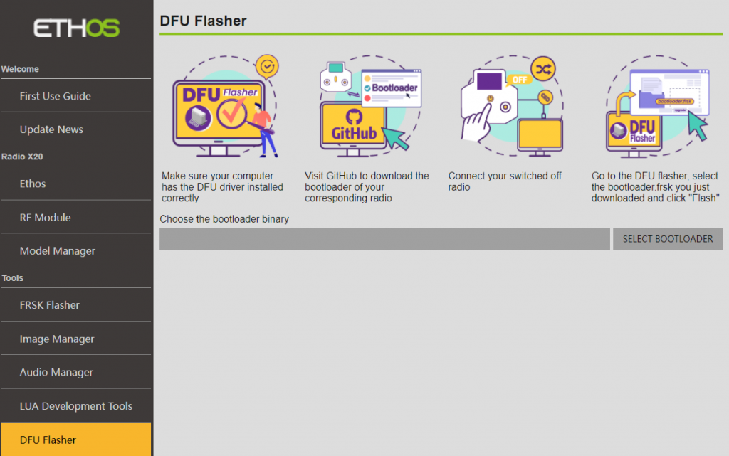
Step 2-2: If you can't connect to the computer normally, please copy this link (https://impulserc.blob.core.windows.net/utilities/ImpulseRC_Driver_Fixer.exe) to download the driver and finish the installation.

Driver as shown in the figure, after opening the SUITE software and connecting the transmitter to the computer, run the driver and wait for the [DFU Burning Tool] on the software to show up.
Step 3: Disconnect the data cable from the transmitter, hold down the [Confirmation Key], and press the [Power Button] of the transmitter to enter Bootloader mode;
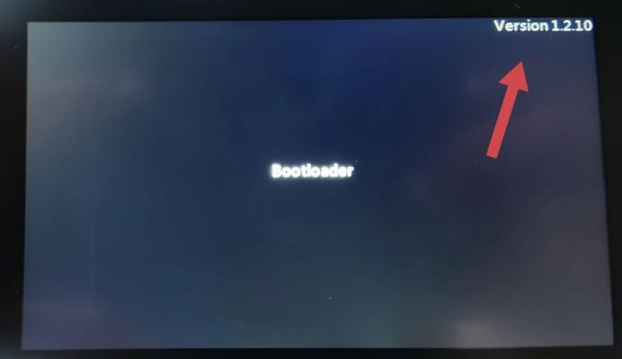
Step 3-1: If the version 1.2.0 or above message appears in the upper right corner of the transmitter screen (as shown in the picture).
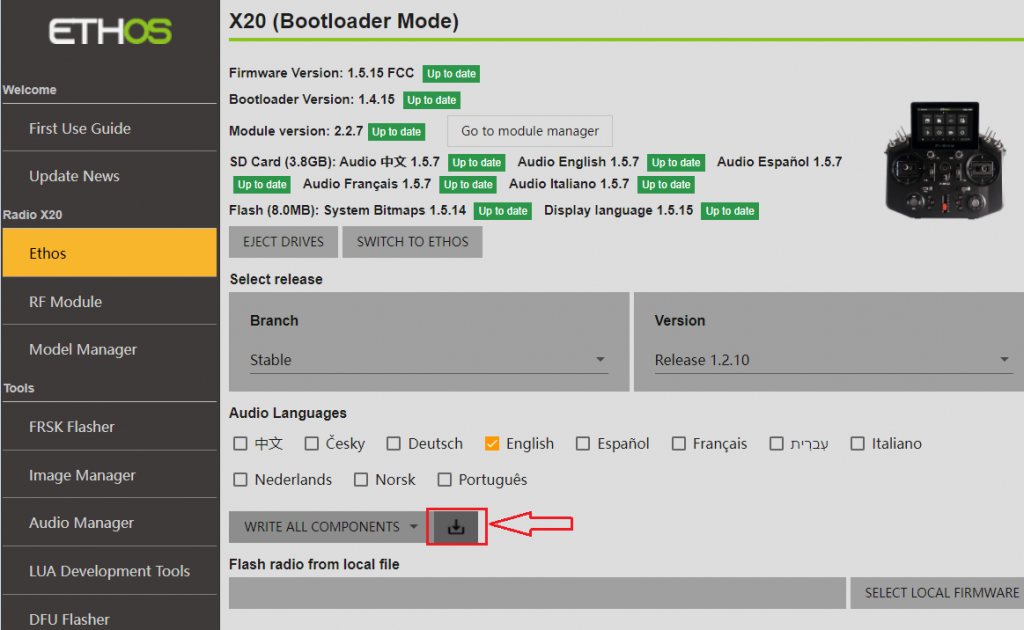
First, open the software, then connect the transmitter, and enter the sidebar menu of the transmitter [X20], where you can read the "system, Bootloader, SD card, and FLASH files".
If there are updates, first select the desired 【audio language】, then choose the content you want to download as needed, and finally click on "Download".
Step 3-2: If the Bootloader version information is not shown in the upper right corner of the screen, it means the Bootloader version number is too low.
You need to disconnect the data cable and turn off the computer, then reconnect the transmitter and computer with the data cable (no need to enter the Bootloader mode again), click the left menu bar [DFU Burning Tool], and then upgrade the Bootloader version of the transmitter to the latest version. After that, you can repeat the above steps 【Step 3 & Step 3-1】 to complete the upgrade of the transmitter.
Download the latest Bootloader version firmware operation as shown below:
1. First, enter the ETHOS official website: https://ethos.frsky-rc.com/

2. Click DOWNLOAD to enter the GitHub system firmware download page.
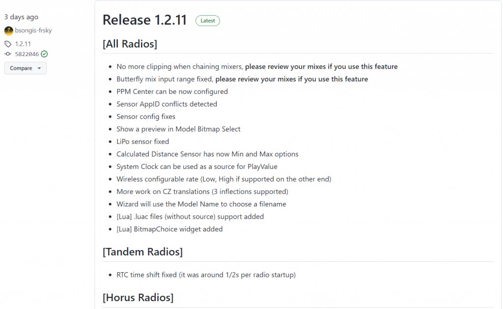
3. Download the BOOTLOADER firmware of the corresponding model of the transmitter you are using.
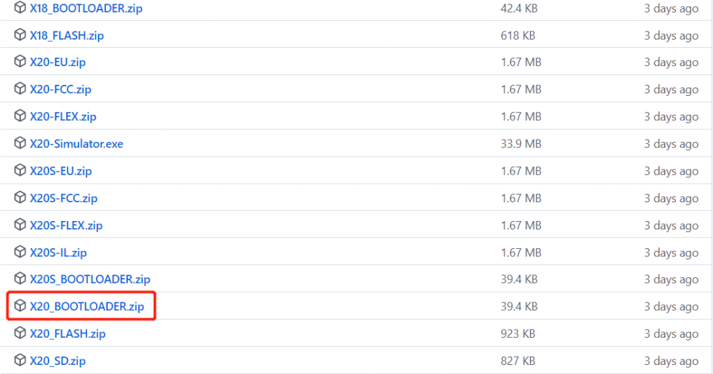
ETHOS SUITE is a software for upgrading the version of FrSky’s ETHOS system and will support more functions in the future. The suite supports all FrSky transmitters of the ETHOS system to perform system upgrades, and the use of this software can simplify the cumbersome steps of upgrading the version of the system and can […]
1. Using the X20 transmitter as an example
First, ensure the transmitter is powered off. While holding down the ”Enter“ key, press the “Power“ button to enter the bootloader screen. Check if there is a version number displayed in the upper-right corner of the screen, as shown in the picture.
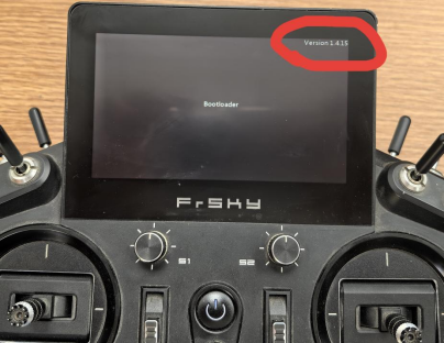
Note: If the version is not displayed, please refer to the tutorial【How to Use the ETHOS SUITE Software】to make the version visible before proceeding with the next steps.
If the version is displayed, proceed directly to Step 2.
2. Go to ethos.frsky-rc.com, download the latest ETHOS Suite installation package from the homepage, then extract and install it.

Note 1: For Windows 10 systems, choose the Windows version (using a version lower than Windows 10 is not recommended as it may cause crashes). For Mac computers, choose the macOS version.
Note 2: The Ethos Suite software version on the website is updated periodically, so please check for updates regularly.
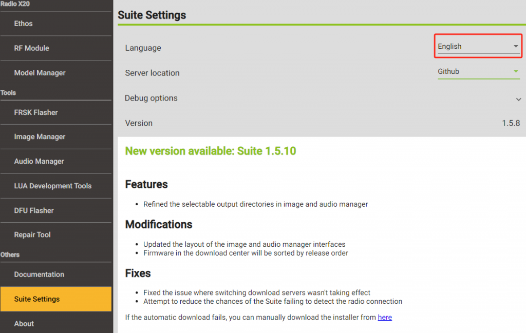
3. Open the Ethos Suite software, find 【Suite settings】 in the left sidebar, change the language you need, as shown in the picture.

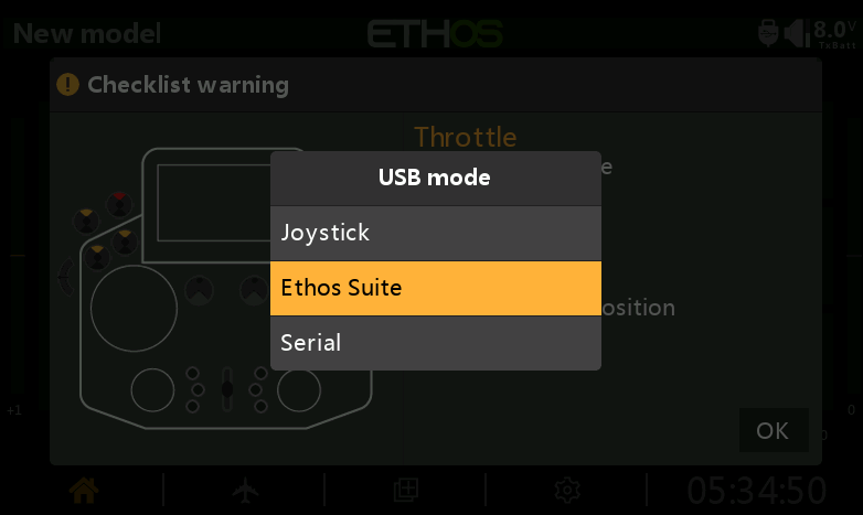
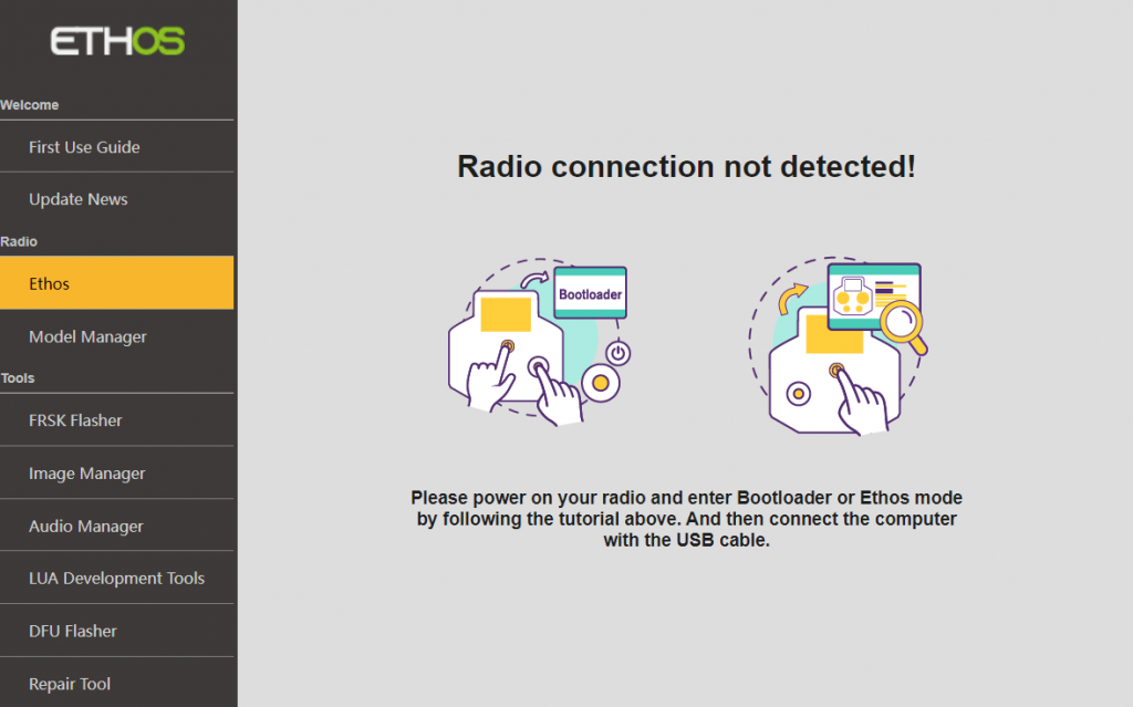
4. Prepare a Type-C data cable. Connect the transmitter to the computer in bootloader mode using the cable, or connect the transmitter to the computer while it is powered on and select the "Ethos Suite" option from the pop-up on the screen to complete the connection.
4-1. If the ETHOS Suite software fails to recognize the transmitter, try using a different data cable or computer, then attempt the connection again. If it still cannot connect, please contact FrSky customer support for assistance.
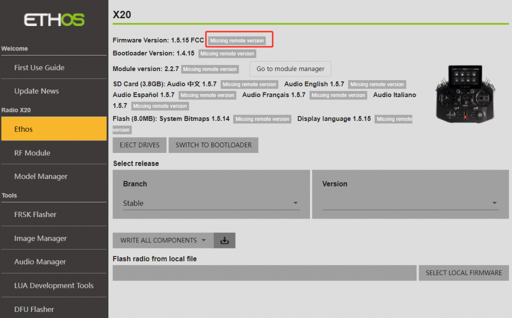
5. After a successful connection, select "Ethos" from the left sidebar. You may encounter the message "Missing remote version" as shown in the picture. You can wait for 2-3 minutes or refresh the page by switching between other options in the left sidebar.
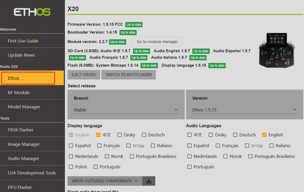
6. Normal display as shown in the image, if [Expired] appears, it means that the current version is not the latest and can be updated.
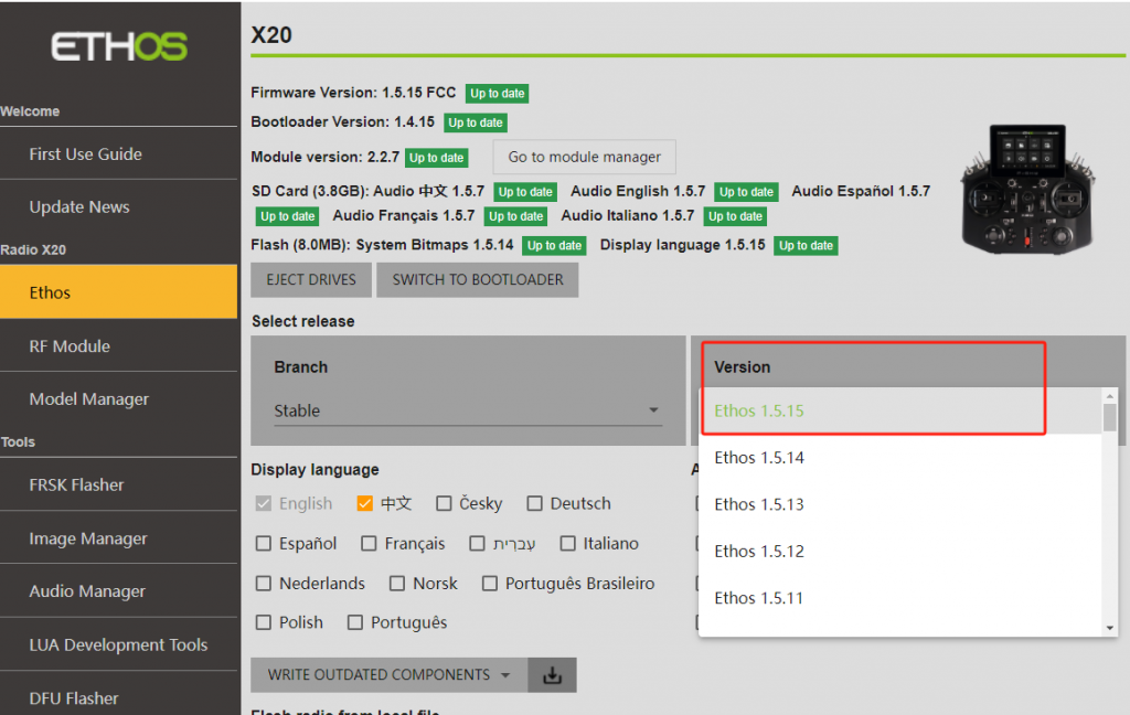
6-1. Click on the 【Version】 option and select the version you want to update to.
6-2. In the 【Display language】 section, choose the preferred system display language; in the 【Audio language】section, select the desired voice pack, as shown in the picture.
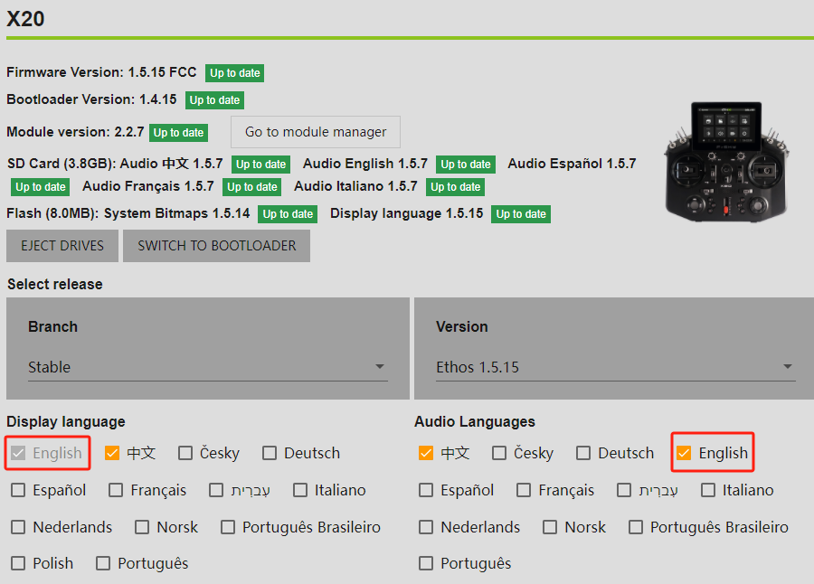
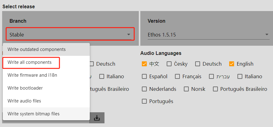
6-3. Click the option within the red box and be sure to select【Write all components】.
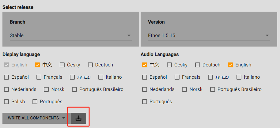
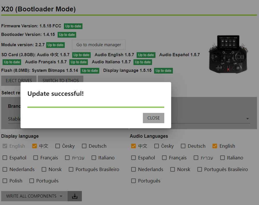
7. Click the "Download" icon to start the upgrade, and wait for the process to complete.
1. Using the X20 transmitter as an example First, ensure the transmitter is powered off. While holding down the ”Enter“ key, press the “Power“ button to enter the bootloader screen. Check if there is a version number displayed in the upper-right corner of the screen, as shown in the picture. Note: If the version is […]
I. How to Update Built-in RF Module?
1. Using the FrSky X20 Transmitter as an example:
Go to FrSky's official website: www.frsky-rc.com, find the corresponding product (X20)--"DOWNLOAD" page, and then download and extract the required firmware from the "RF FIRMWARE" section.


2. Power off the transmitter, and hold down the "Enter" while pressing the "Power" button to enter the bootloader screen. Connect the transmitter to the computer using a Type-C data cable. Once the computer recognizes the transmitter's memory card drive, double-click to open it, as shown in the image.

2-1. If you are using a transmitter with built-in storage (such as the X18, X18S, X20R, etc.), the memory drive will be labeled as "RADIO" or "NAND," as shown in the image.

3. Place the extracted firmware into the root directory of the memory card drive, as shown in the image.

4. After importing is complete, power on the transmitter, press the physical "SYS" button and navigate to System Menu→File Manager to find the RF firmware.

5. Press the "Enter" and select "Upgrade Built-in Module" as shown in the image.

6. Wait for the upgrade, then click "Close" to finish the update.

Ⅱ. How to Update External RF Module?
1. Using the FrSky X20 Transmitter & Twin Lite Pro RF module as an example:
Go to FrSky's official website: www.frsky-rc.com, find the corresponding product (X20)--"DOWNLOAD" page, and then download and extract the required firmware from the "RF FIRMWARE" section.


2. Power off the transmitter, and hold down the "Enter" while pressing the "Power" button to enter the bootloader screen. Connect the transmitter to the computer using a Type-C data cable. Once the computer recognizes the transmitter's memory card drive, double-click to open it, as shown in the image.

2-1. If you are using a transmitter with built-in storage (such as the X18, X18S, X20R, etc.), the memory drive will be labeled as "RADIO" or "NAND," as shown in the image.

3. Place the extracted firmware into the root directory of the memory card drive, as shown in the image.

4. After the import is complete, power on the transmitter, press the physical "SYS" button and enter to
【System Menu——File Manager】to find the RF module firmware.

5. Press the "Enter" and select "Upgrade External Module" as shown in the image.

6. Wait for the upgrade, then click "Close" to finish the update.

I. How to Update Built-in RF Module? 1. Using the FrSky X20 Transmitter as an example: Go to FrSky’s official website: www.frsky-rc.com, find the corresponding product (X20)–“DOWNLOAD” page, and then download and extract the required firmware from the “RF FIRMWARE” section. 2. Power off the transmitter, and hold down the “Enter” while pressing the “Power” […]
1. Make sure the transmitter system has been updated to version 1.4.0 and above.
Take the FrSky X20S transmitter as an example:
2. Turn off the transmitter, press and hold the [Confirm Button] and the [Power Button] at the same time to enter the 【Bootloader 】interface, and after the computer recognizes the TF card memory disk of the transmitter, double-click to open it, as shown in the figure below:
2-1: If you are using a transmitter with built-in storage (such as X18/X18S/X20R), the memory disk name will be displayed as RADIO or NAND, as shown in the image below:
Note: For users of transmitters with built-in memory disks like the X18/X18S/X20R, who want to use a TF card, the disk name will be displayed as in Step 2. You can then select the storage location in the transmitter under 【General Settings -- Storage Location】
3. Find the 【bitmaps】 folder in the memory disk and open it.
4. Find the 【Models】 folder. If not, you can re-create it yourself.
5. Open the 【Models】 folder and put in the picture of the DIY model image you made.
The image requirements are as follows:
①Choose BMP or PNG format based on your needs.
Note: The difference is that PNG format requires 4 bytes per pixel to store its color information and supports transparency, while BMP format only requires 3 bytes but no color richness for a smaller file size.
②The file name, including the extension, should be no more than 15 bytes.
③The resolution of the image cannot exceed the resolution of the transmitter screen.
④The larger the image memory size, the more laggy it will display on the transmitter; conversely, smaller images will display more smoothly.
6. Once the image import is complete, power on the transmitter, go to 【Model Menu -- Edit Model -- Image】, and you will see the DIY model image.
7. If the image cannot be displayed, you can use the ETHOS SUITE software -- 【Image Manager】 to convert the format.
Put the converted image back into the Models folder, then go to 【Edit Model -- Image】to view it.
1. Make sure the transmitter system has been updated to version 1.4.0 and above. Take the FrSky X20S transmitter as an example: 2. Turn off the transmitter, press and hold the [Confirm Button] and the [Power Button] at the same time to enter the 【Bootloader 】interface, and after the computer recognizes the TF card memory […]
1. The transmitter system is 1.5.0 and above
Take the X20S transmitter as an example
1. First make sure that the system of the transmitter is 1.5.0 or above (including 1.5.0)
2. Turn off the transmitter, press and hold the [Confirm Button] and press the [Power Button] at the same time to enter the bootloader interface, at this time, connect the transmitter to the computer through the data cable, and after the computer recognizes the TF card memory disk of the transmitter, double-click to open it, as shown in the figure below:
Note 1: If it is a transmitter with built-in storage (e.g. X18/X18S/X20R, etc.), the name of the memory disk is displayed as RADIO or NAND, as shown in the figure below:
Note 2: If you are using a TF card on a transmitter with built-in storage, the disk name displayed after connecting to the computer is the same as that in step 2. Using the transmitter's built-in storage or TF card, you can set it in the transmitter's [General Settings - Storage Location].
3. Find the voice folder in the corresponding language path and put it into the DIY voice file in .wav format
Example: The Chinese voice path is audio\cn\default
Note 1: Do not place it in the system folder
Note 2: cn means Chinese, en means English, fr means French, etc., and the voice file is placed in the voice folder of the corresponding language.
4. Turn on the transmitter, enter [System Menu - General Settings - Audio], set [Language] to the corresponding language, and [Sound 1 (Main)] to the voice folder of the voice file in step 3 above, then you can recognize and use the homemade voice file.
NOTE: If the audio is not recognized in subsequent use, you can use the ethos suite software - audio manager to convert the format
2. The transmitter system is a version below 1.5.0
Take the X20S transmitter as an example
1.First, make sure that the transmitter's system is version 1.5.0 or lower (excluding 1.5.0)
2. Turn off the transmitter, press and hold the [Confirm Button] and press the [Power Button] at the same time to enter the bootloader interface, at this time, connect the transmitter to the computer through the data cable, and after the computer recognizes the TF card memory disk of the transmitter, double-click to open it, as shown in the figure below:
Note 1: If it is a transmitter with built-in storage (e.g. X18/X18S/X20R, etc.), the name of the memory disk is displayed as RADIO or NAND, as shown in the figure below:
Note 2: If you are using a TF card on a transmitter with built-in storage, the disk name displayed after connecting to the computer is the same as that in step 2. Using the transmitter's built-in storage or TF card, you can set it in the transmitter's [General Settings - Storage Location].|
3. Open the memory disk, find the audio folder and open it, put in the DIY voice file in .wav format
Note: Do not put DIY audio files into subfolders such as cn/en
4. Turn on the transmitter and you can use DIY voice
NOTE: If the audio is not recognized in subsequent use, you can use the ethos suite software - audio manager to convert the format
1. The transmitter system is 1.5.0 and above Take the X20S transmitter as an example 1. First make sure that the system of the transmitter is 1.5.0 or above (including 1.5.0) 2. Turn off the transmitter, press and hold the [Confirm Button] and press the [Power Button] at the same time to enter the bootloader […]